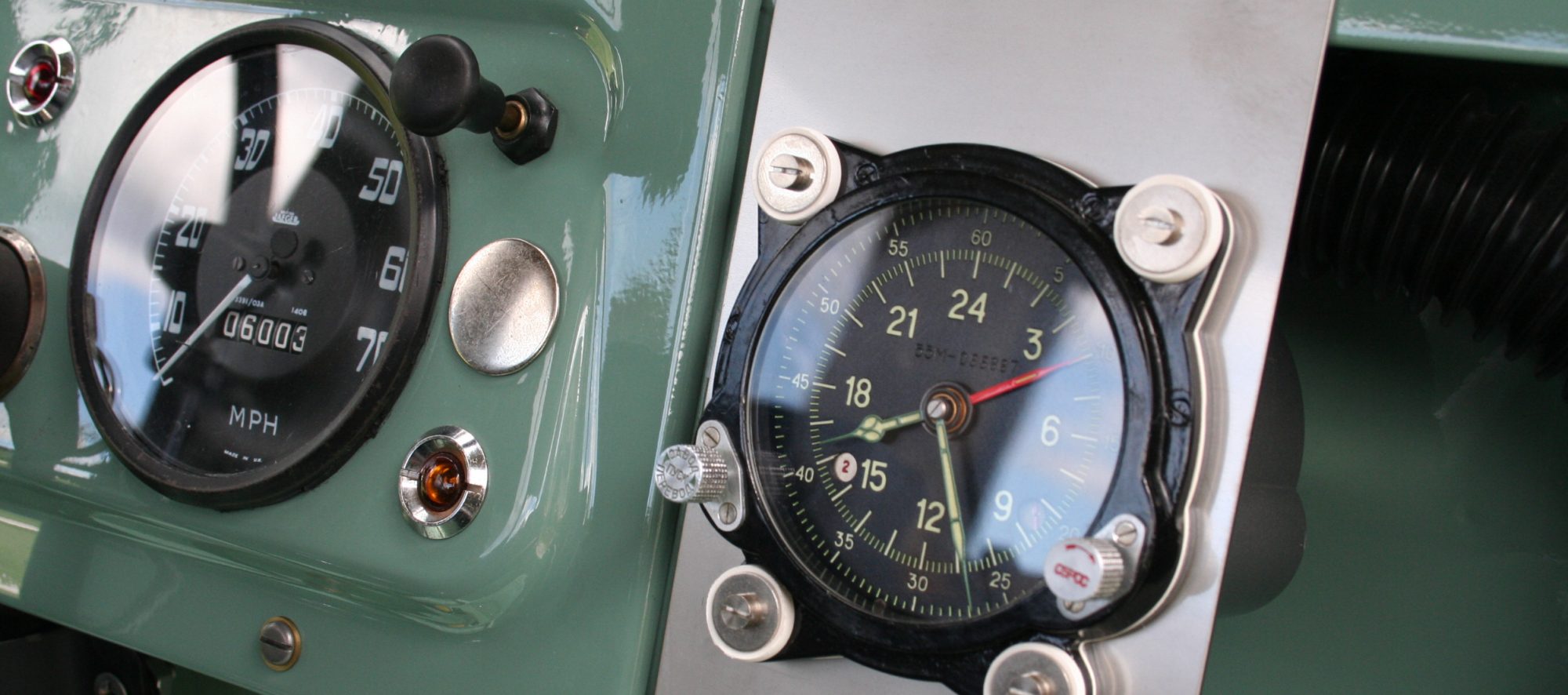

Seems there are three popular choices……….IH Scout, Range Rover P38, or Toyota FJ. I initially went with the P38 steering gear, but felt it was just too big (vertically it takes quite a bite out of the inner fender) Scout boxes are getting hard to find, so I went on the hunt for an FJ60 gear (on the advice of Jim Young / Series Trek). I found one at a wrecking yard in New Hampshire. Pretty ugly on the outside, but once opened it was in nice shape internally.

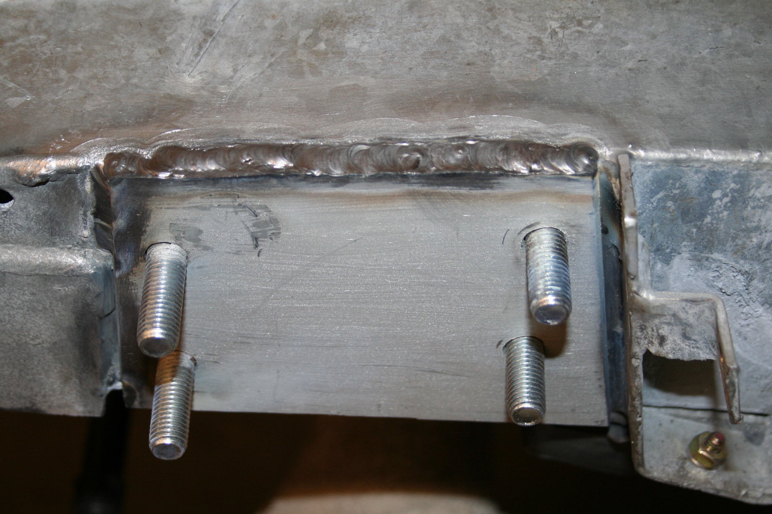
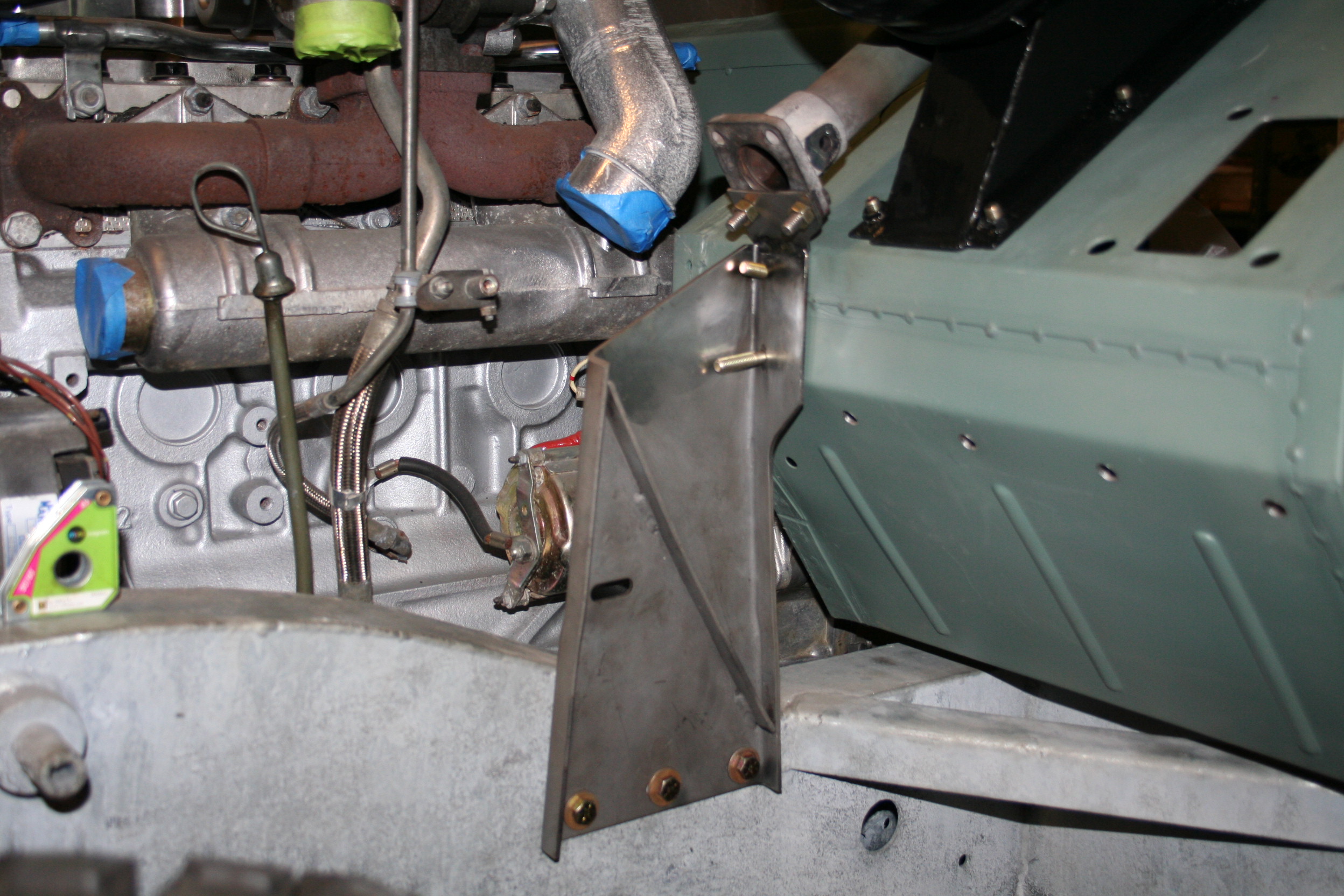
Holes bored in the frame. Backing plate with two grade 8 studs welded up. The plate will add some strength to the frame where the steering gear mounts.

Guide tubes will be welded into the frame.


Plate in place and clamped firmly so it doesn’t shift during welding.
Welded in place

Steering gear in place.

Worm gear cut off Series 2 shaft. A length of steering shaft from Borgeson turned down on a lathe and inserted into the stock shaft. These will be tig welded together.

The Borgeson shaft and Series 2 shaft prepped, beveled and ready to weld.
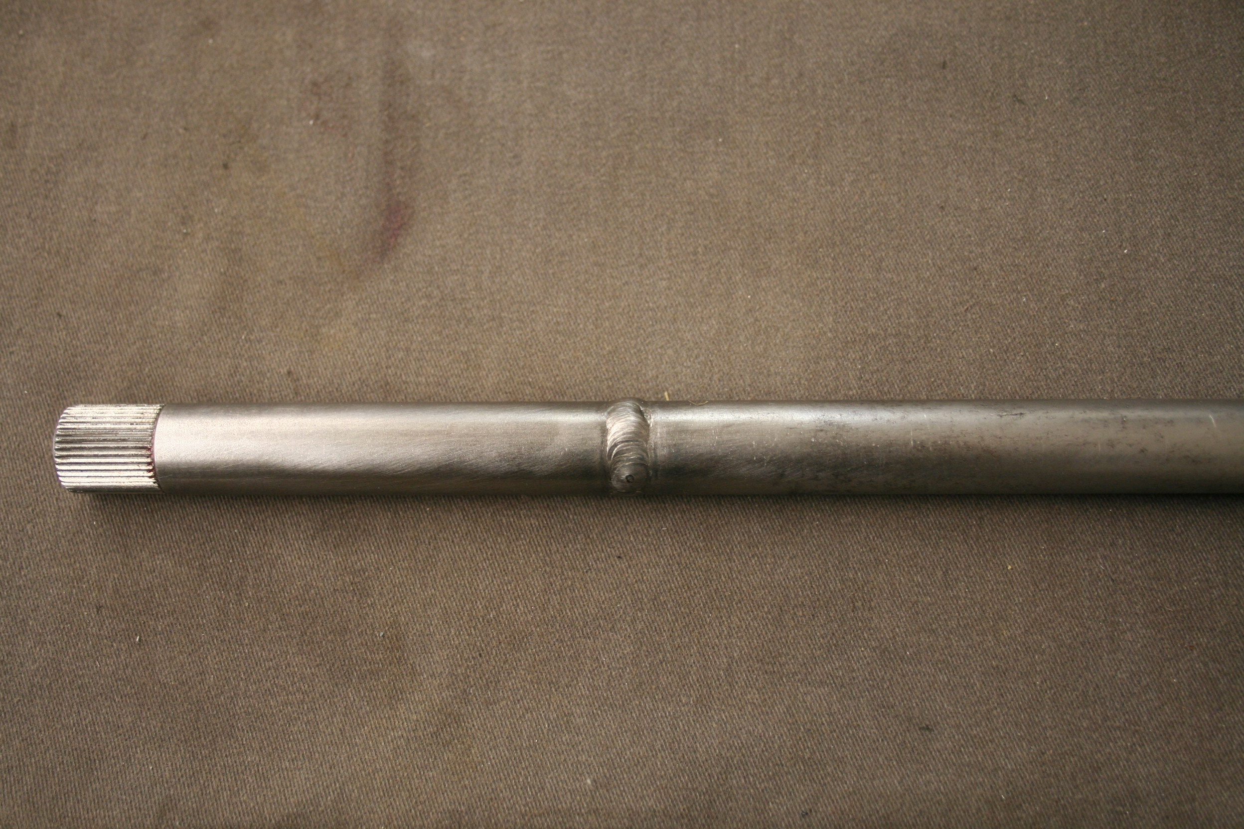
Welded.

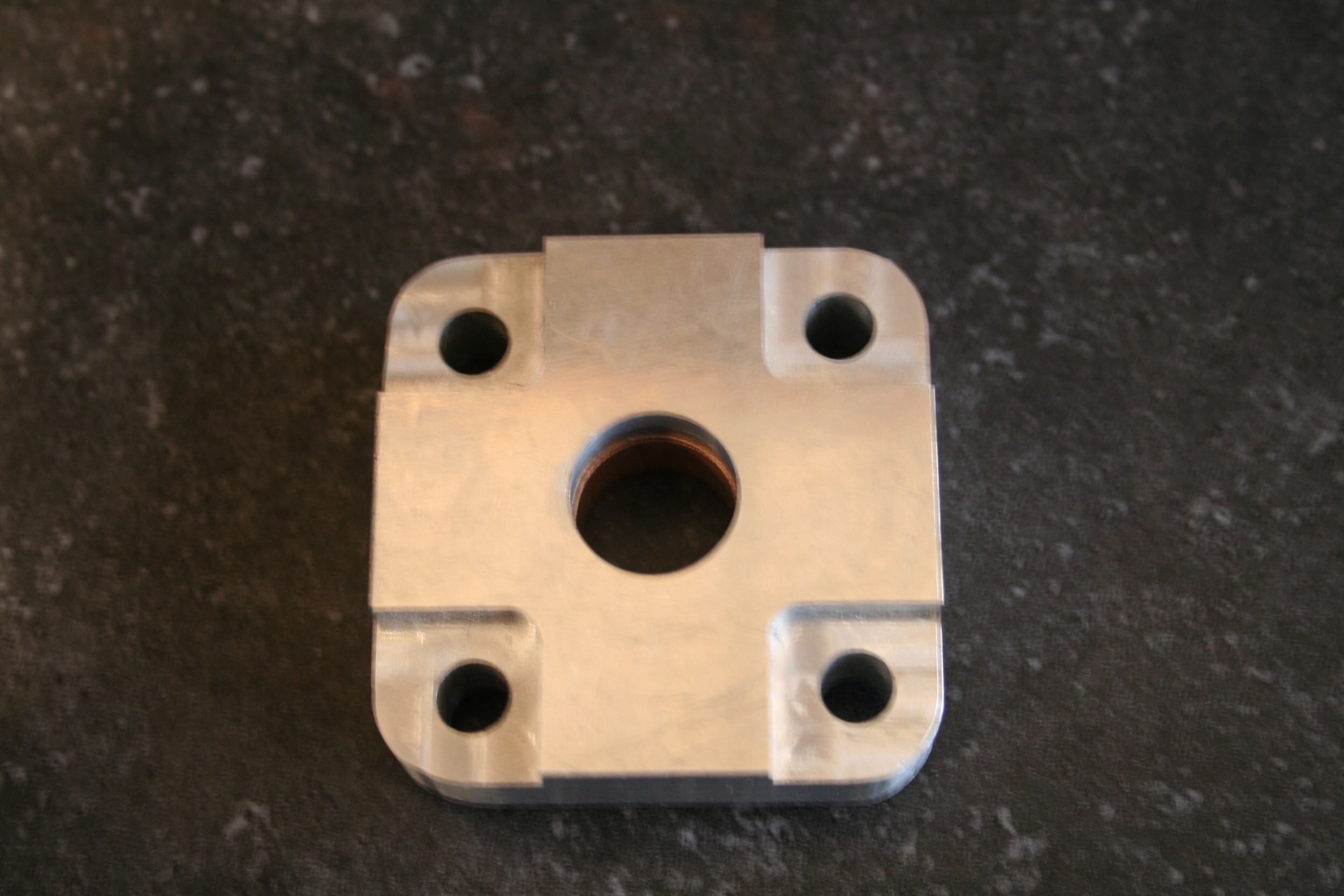
The bearing carrier, which mimics the part used by Pangolin 4×4 in their conversions (first seen on their “Pabst Blue Rover”), made with pressed in bronze bearing will mount to the modified bulkhead support. This will support the modified steering shaft inside the stock steering column.

Carrier and steering shaft in position.

Borgeson to the rescue once again with two universals and collapsable “cut to fit” steering shaft.
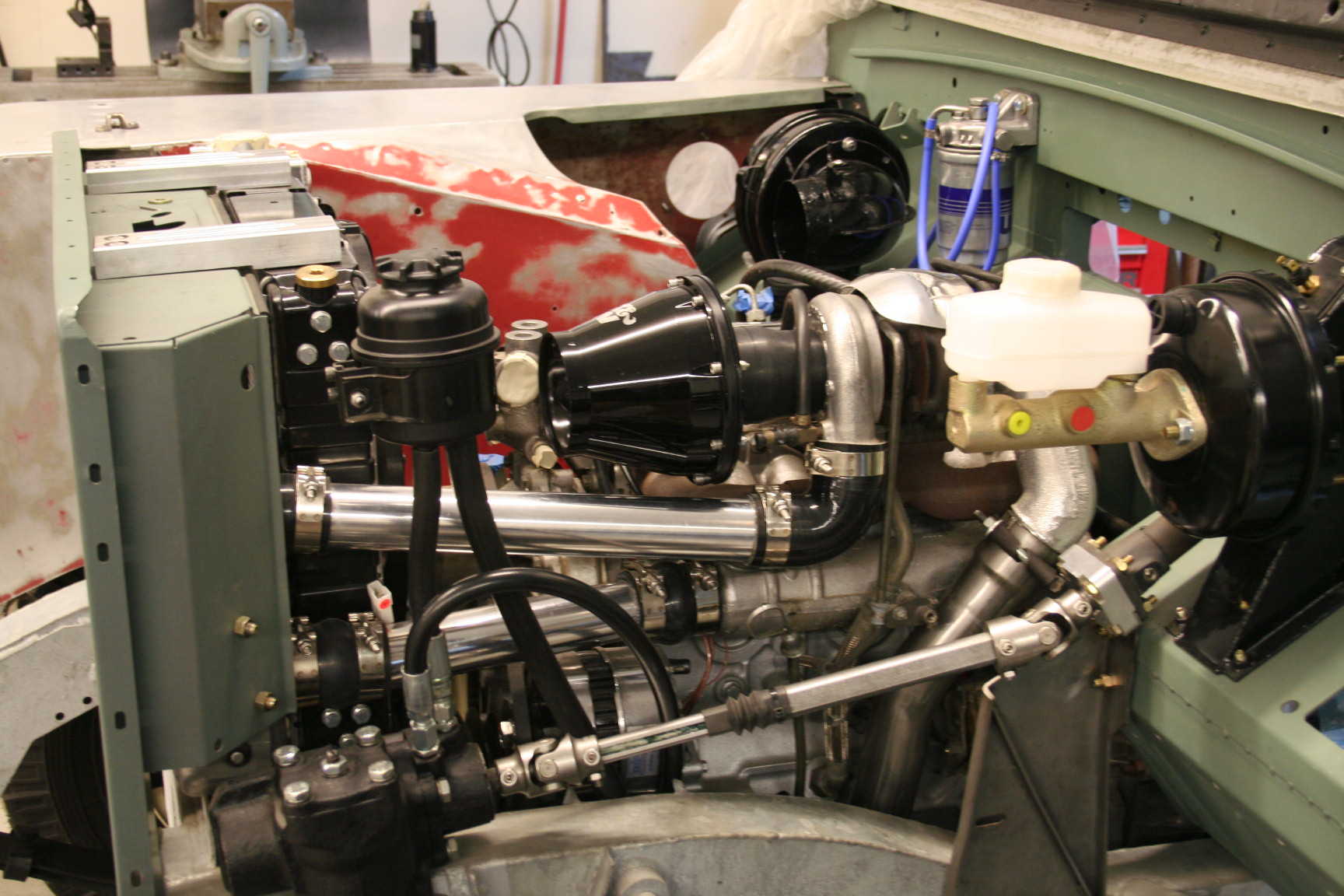
The stock Defender reservoir is used along with the power steering pump located under the alternator. I had a local heavy truck dealer make up the lines for me.
Colby, I love your build! I have two questions about the steering mods please.
1. Do you have a picture of the modified bulkhead support bracket? I can imagine what it looks like but wouldn’t mine seeing it.
2. Would you happen to have kept track of the bushing specs you used, or relay how to choose the right one (I assume an ID within some tolerance?)
Thanks,
charles
Hi Charles,
The bearing used is from McMaster Carr, their part number is 1677K15. It’s a PTFE/oil-lubricated bronze bearing for a 3/4″ shaft. I’ve added another photo of the support bracket on the site, it’s the best I have. In the photo the support is still mounted to the frame, but without the bearing carrier so you can get a better idea of how it looks.
Hope this helps, please write if you need any other info.,
Colby
Very clean steering mod! A quick question. What do you use to restrict the axial movement of the steering inner shaft with respect to the outer tube? Do you rely on the u-joint to prevent the steering inner shaft from working it’s way up the steering column? I know the steering wheel would prevent it from going the other direction.
thanks!
Hi Carl,
That movement was a concern in the design, and I’m certainly no engineer, but what I ended up doing was countersinking the set screw in the upper u-joint into the inner shaft. In the event of a front end collision I would hope between the countersunk set screw and the collapsible intermediate shaft it would keep the steering column from becoming a weapon……….then you just have to worry about the rest of the metal that’s going to come flying at you in a Series Rover accident!
I have a question about how you mounted the pump. It looks like the front mounts are studs made from bolts welded to the back side of the plate. This would explain the enlarged holes in the frame. The rear mounts appear to be bolts run though the width of the frame with crush tubes welded in for support. I’m assuming you did it like this because the crossmember was in the way of the front mounts, and you ran bolts through the frame for the rear mounts to take advantage of the full support of the frame.
Your work is top notch and a huge help with my project. Thank you!
Thanks very much for the compliment. All of your assumptions are correct about the design, glad to hear that this helped with your project.